
When you determine the sequence of activities in a project you need to pay attention to dependencies between these activities. Some activities might require predecessor or successor activities to be completed or started before they can be started or completed themselves. According to the Guide to the Project Management Body of Knowledge (PMBOK®, 6th ed., ch. 6.3.2), this is done by applying a technique called precedence diagramming method (PDM).
In this article, you will learn what PDM is about, incl. the logical relationships covered by the method and an example of its use in practice.
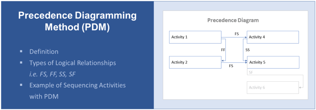
What Is the Precedence Diagramming Method (PDM)?
PDM is a scheduling technique of the ‘sequence activities’ process in PMI methodology. The precedence diagramming method can be used for creating a project schedule network diagram which is an output of this process that is used as an input for the ‘develop schedule’ process (PMBOK, ch. 6.3.2, 6.5).
The method involves the identification and visualization of the sequence and dependencies of activities in a project or a part of a project, such as a workstream or a work package.
The model can reflect 4 types of dependencies – also referred to as logical relationships – that are introduced in the next section. These dependencies form the connection between successor activities and predecessor activities which are shown as nodes in the diagram. This is similar to the activity-on-node or activity-on arrow method yet more flexible as it allows overlaps of activities (source).
What Are the Types of Dependencies in PDM?
The 4 types of logical relationships in the precedence diagraming method are:
- Finish-to-Start (FS) dependency,
- Finish-to-Finish (FF) dependency,
- Start-to-Start (SS) dependency, and
- Start-to-Finish (SF).
You can memorize the concept as follows: The first part (‘finish’ in ‘finish-to-start’, for instance) refers to the status the predecessor activity must obtain for the successor activity to achieve the status expressed in the second part (‘start’ in FS).
Read on for a definition and illustration of each of these types. In the next section, we are sharing an example of these dependencies in practice.
If activities are linked through more than one logical relationship the more important one should be prioritized to avoid complexity and circular references in the diagram.
If activities can start earlier or need to be delayed in a sequence, so-called leads and lags need to be incorporated. Learn more about leads and lags in this article.
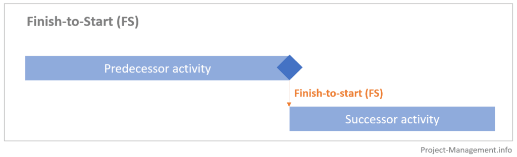
Finish-to-Start Relationship (FS)
If two activities are linked by a finish-to-start dependency, this means that the predecessor activity must be completed before the successor activity can start.
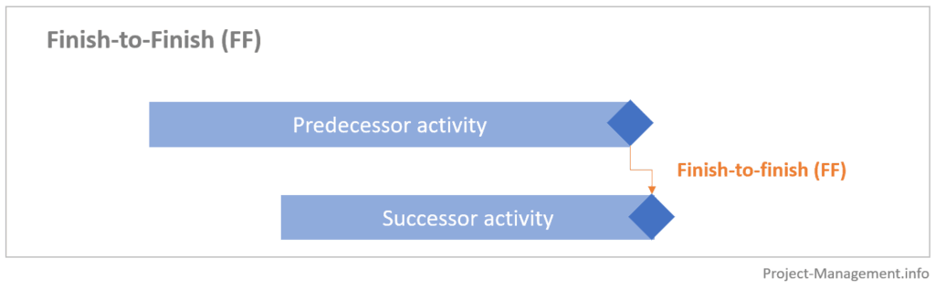
Finish-to-Finish Relationship (FF)
Under this type of logical relationship, a successor activity requires the predecessor activity to be finished before it can be completed.
This type of dependency can also coincide with start-to-start relationships of the same activities.
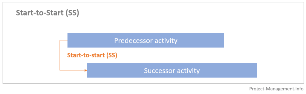
Start-to-Start Relationship (SS)
If two activities are connected through a start-to-start dependency, this means that the predecessor activity must have started before the successor activity can start.
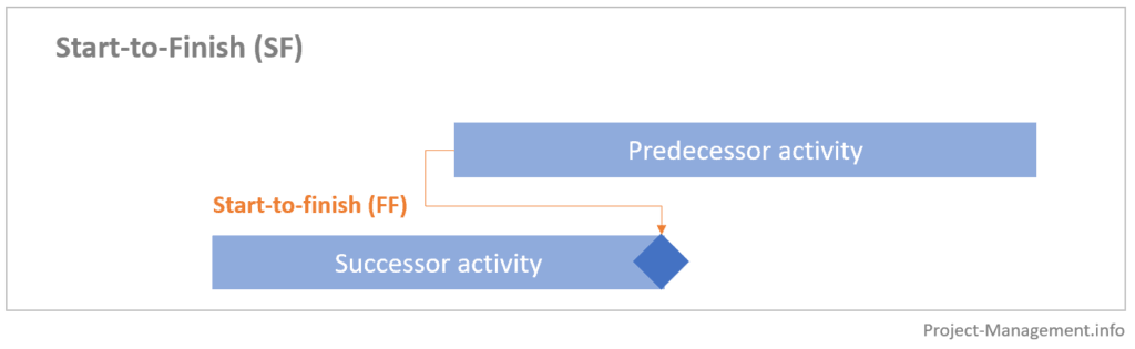
Start-to-Finish Relationship (SF)
This logical relationship requires that a predecessor activity must have started before the successor activity can be finished. In practice, this type of dependency does not occur very often which is also acknowledged by the PMBOK.
Example of Precedence Diagramming Method
This example of PDM modeling refers to a fictional software development project. However, you can replace the IT-related aspects with activities from other areas such as construction, research and development, strategy development and implementation, etc. As for many project management techniques, PDM as a method can be applied to almost any kind of project.
The first 4 activities and durations in this example are consistent with the example presented in our article on leads and lags, so you can compare the results and differences between both techniques.
Activities and Their Dependencies
The project involves designing, developing, implementing, testing and deploying an IT solution. For the sake of conciseness, we will only sequence the following design and development activities for 2 modules:
- technical design of module A (duration: 10 days),
- technical design of module B (duration: 5 days),
- development of module A (duration: 15 days),
- development of module B (duration: 20 days), and
- development of feature F in module B (duration: 1 day).
The technical dependencies are:
- The technical design of module B cannot finish until the technical design of module A has been completed.
- The technical designs of module A must be completed before the module A development can start.
- The technical designs of module B must be completed before the module B development can start.
- The development of module B can only be started when the development of module A has been started.
- The development of feature F cannot be finished before the development of module B has started (although it can be developed independently, it needs to be integrated into module B)
Logical Relationships and Precedence Diagram
For the creation of the PDM, these technical interdependencies need to be translated into logical relationships such as FS, FF, SS and SF. This is illustrated in the following table.
| Technical dependencies | Logical relationship |
| The technical design of module B cannot finish until the technical design of module A has been completed. | Activity (1) is predecessor of activity (2) in a finish-to-finish (FF) dependency (There could also be a start-to-start (SS) dependency between (1) and (2) but the FF relationship is prioritized as its impact is higher) |
| The technical designs of module A must be completed before module A development can start. | Activity (1) is predecessor of activity (3) in a finish-to-start (FS) relationship |
| The technical designs of module B must be completed before module B development can start. | Activity (2) is predecessor of activity (4) in a finish-to-start (FS) relationship |
| The development of module B can only be started when the development of module A has been started. | Activity (3) is predecessor of activity (4) in a start-to-start (SS) relationship |
| The development of feature F cannot be finished before the development of module B has started | Activity (5) is a successor of activity (4) and in a start-to-finish (SF) relationship |
Note that the dependencies in this table deviate from those in the example in the leads and lags article for illustration purposes.
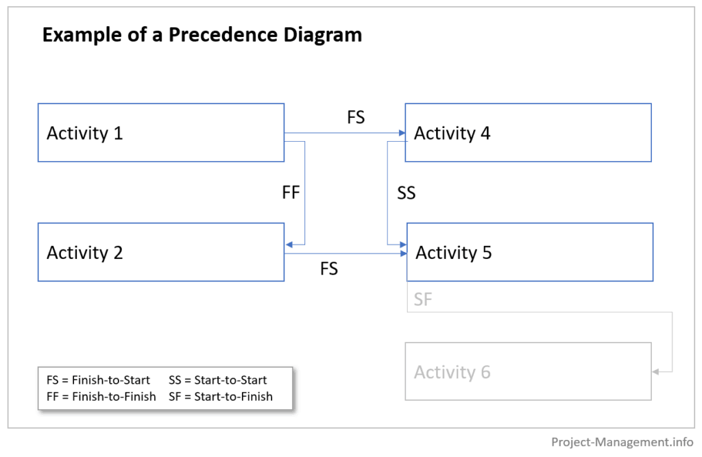
Translated into a precedence diagram, the sequence of activities looks as follows:
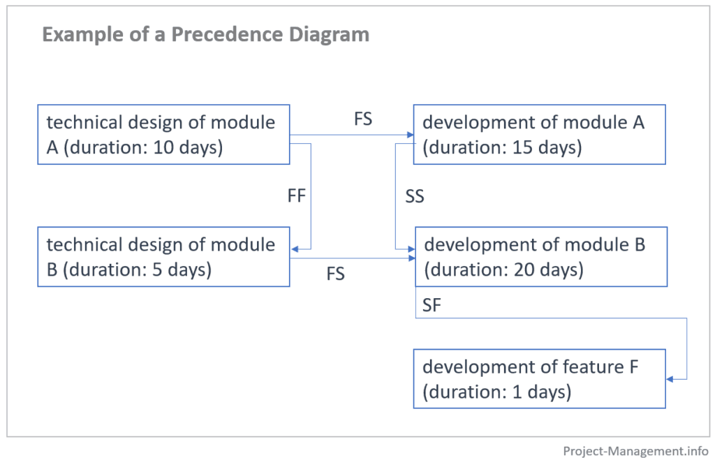
You can then use this diagram to determine the total duration of a project or – in this case – the work packages “technical design” and “development”. Under the assumption that no constraints other than logical relationships exist (no resource or material constraints, for instance), the sequence and schedule could be as follows
- The design and development of module A take 25 days (10 days design + 15 days development).
- The design and development of module B would take 25 days (5 days design + 20 days development). However, the design of module B cannot be finished until the design of module A has been completed which takes 10 days. Thus, the path for the design and development of module B is 30 days (20 days development + 10 days design of module A which is longer than the 5 days FF-related activity design of module B). In our example, this would also be the critical path, i.e. the chain of activities with the longest total duration.
- Developing feature D takes 1 day and can take place within the timeframe of the development of module B. Thus, it does not affect the overall duration.
Conclusion
The precedence diagramming method is a useful and common technique to determine and visualize logical relationships between activities. PDM is also an area that may be covered in the PMP exam.
Its results also serve as an input to the development of the project schedule baseline: When sequencing and scheduling activities, one of the goals is finding the critical path, the longest (by means of duration) sequence of activities that defines the minimum project duration (source). The PDM is a tool that can be used for preparing relevant input data for the critical path method.